The implementation of seismic surveys involves several departments working in and in contact with each other. The departments involved include: Topography, Seismologist, Processing, Field Quality Control (QC) and other support departments. Dept. Topography is tasked with plotting the theorical coordinates of the design results. Dept. Seismologist is tasked with starting from cable deployment, placement of Shot point (drilling and preloading process) and subsequently carried out shooting and recording that technical implementation is carried out in LABO. The recording data is processed by the processing department to obtain the final data output of the survey implementation. To control and improve the quality in seismic data acquisition activities, Field QC is also carried out.
Here's an overview of seismic survey work.
Topography
In seismic surveys the position of coordintat SP (shot point)and TR (trace)is very important to be considered, because it concerns the quality of the data to be generated. The Department of Topography conducts the exploration of the coordinates of the theoretical SP and TR coordinates that have been designed. In creating a seismic survey design there are several field parameters to be aware of:
1. Trace interval : Distance between each trace
2. Shot point interval: distance between one SP and the other SP
3. Far Offset: The distance between the seismic source and the furthest trace
4. Near Offset: The distance between the seismic source and the nearest trace
5. Number of shot points: The number of SP used in a single path
6. Number of Traces: The number of traces used in a single SP
7. Record length of time recording seismic waves
8. fold coverage: The number or frequent of a point in the subsurfece recorded by the geophone on the surface
The work program carried out by the Topography department include:
Location Survey
- Survey Location Position
- Condition of Survey Area
- Access to survey locations
- Job Planning
- Work map creation
Control Point Measurement
The first step in creating a control point is to distribute GPS pillars throughout the area. Then this GPS BM is installed in the survey area according to the distribution in which the pillar is installed.
Known BM points are used to determine other unknown coordinates, such as shoot point coordinates or receiver coordinates. Basically GPS measurements are always tied to points from Bakosurtanal that aim to bind coordinate points globally so that they can be correlated with other map coordinate points.

Seismic Trajectory Measurement
- Seismic Trajectory Measurement & SP and TR Peg InstallationSeismic trajectory measurements including firing point (SP) and record point (TR) measurements are performed using total station equipment.
- Titian Making and PilotingTitian is made to facilitate and facilitate work when the survey finds impassable locations such as: irrigation, trenches, rivers or swamps So as to effectively time and work crew both drilling and recording.

Trajectory Measurement
DRILLING AND PRELOADING
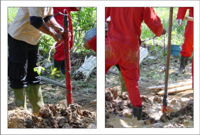
Shallow drilling in seismic surveys aims to create a place to plant dynamite as a source of energy in recording. The depth of the drill hole is usually 30 m with a diameter of about 11 cm. The determination of the depth of this drill hole is based on previous test experiments. This depth is located under theweathering zone.

Drilling
PRELOADING
In seismic surveys used dynamite energy sources for onshore, and airguns were used specifically for survey areas in the water. The dynamite used with the Power Gel brand is encased in a plastic tube and can be connected according to the desired weight to be planted. Inside this tube dynamite is filled with a detenator or'cap'as the source of the first explosion, and also installed anchors to keep dynamite firmly stuck in the ground.
Preloading iscarried out immediatelyafter drilling is complete, with the aim of avoiding the effects of superficiality and collapse in the hole. The filling of dynamite is carried out by a loader squad led by a shooter who has knowledge of security related to explosives and already has a written license from MIGAS.

Preloading

Recording
Recording is the final work of the acquisition of seismic data, namely recording seismic data into magnetic tape (tape)which will be processed by the data processing center (processing center). Before recording the cable is presented according to its position and trajectory based on the design of the 2D survey. At the time of recording, the one in control is an observer using a recording equipment called LABO.

Equipment Preparation
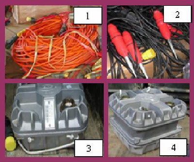
Equipment used in the recording process include:
1. Trace Cable: Trace connecting cable.
2. Geophone: The vibration receiver of the source wave is an analog signal.
3. SU (Unit Station): Converts analog signals from trace into digital to be transferred to LABO.
4. PSU (Power Station Unit): Works to provide energy on SU 70 A/16 Volt.
Shooting
When blasting and recording not all data is perfectly recorded, sometimes dynamite does not explode, Up Hole is not recorded properly, a lot of noise, etc. This event is called misfire, a few misfire terms that are often used in the field:
- Cap Only : dynamite does not explode, the detenator explodes
- Dead Cap : short relationship, unimplploded dynamite
- Loss wire : deto cable not found
- Weak Shot : weak shot, low frequency
- Line Cut : cable disconnected during shooting
- Parity Error : instrument problem
- No CTB : no confirmation time break
- Loss Hole : no dynamite hole found
- Reverse Polaritty : reverse polarity
- Bad/No Up Hole : UpHole is ugly or none (on monitor record or blaster)
- Dead Trace : trace off
- Noise Trace : there is noise in the trace
FIELD PROCESSING
Field processing is a process carried out in the field before the next process is carried out at the center. The main concern in field processing is in the geometry of the shooting where if there is a wrong ID, wrong coordinate, wrong spread etc., it can be known and immediately confirmed to field seismologist and TOPO for improvement. The process of processing seismic data in the field is usually only done until the final stage of the stack dependingon the client's request. Common steps in processing seismic data in the field are as follows:
Loading Tape
Sessionmic data in today's technology is always stored in magnetic tape in certain formats. The magnetic tape that contains this field data is called field tape. The SEG (Society of Exploratory Geophysics) has set a standard data writing format on magnetic bands.
Geometry Up Date
It is the process of defining the identity of each trace associated with shotpoint, X,Y,Z coordinates on the surface, CDP sets, offsets against shot-points, and so on.
Trace Editing
The editing and mute process aims to change or correct traces or records of unwanted things obtained from recording data in the field.
Editing can be done on some bad traces due to noise, especially coherent noise, misfire, or trace that dies, polarity is reversed. The implementation of editing can be done in 2 ways, namely, first making those unwanted traces to zero (EDIT) and or discarding/cutting trace parts in the zone to be defined (MUTE).
Things that need to be edited from a data can be obtained from the observer report as well as by observations from the raw record display.

Raw Data
Static Correction
The purpose of this static correction is to obtain arrival time when the shooting is carried out with a firing point and geophone group located in a horizontal plane and in the absence of a weathered layer. This correction is done to remove the influence of topographic variations, weathered layer thickness and speed variations on weathered layers. A flat reflector willbedisturbed by static conditions caused by thenear surface efects.
In general this static correction can be divided into two parts correction:
-Weathering layer correction)
- Altitude Correction
Amplitude Recovery
This process aims to recover the reduced amplitude value lost due to seismic wave tethering from source to geophone, in such a way that each trace is multiplied by a certain magnitude, so that the amplitude value is relatively stable dare time break to the target depth. This reduction in seismic wave intensity is due to the following:
- Damping because it passes through less elastic rocks so that it amprifies wave energy.
- The spread of energy in all directions(spherical spreading or spherical divergence).
Deconvolution
The vibration energy sent into the earth undergoes the process offilteringthe earth as a filter against the seismic energy. Due to the effect of the earth filter, the form of seismic energy (wavelet)that was sharp and high amplitude in the time domain. When reviewed in the frequency region, it appears that the amplitude spectrum becomes narrower because the amplitude of high frequencies is muted by the earth and the phase spectrum changes unevenly. Deconvolution is a process for compensating the earth filter effect, meaning that within the time region the wavelet form is sharpened again, or within the frequency region the amplitude spectrum is flattened and the phase spectrum is zeroed or minimized.
Speed Analysis
Velocity analysis is amethod used to obtain velocity stacking from seismic data conducted using Interactive Velocity Analysis obtained from NMO speed assuming that the NMO curve is hyperbolic. This speed analysis is very important, because with this speed analysis will be obtained a speed value that is accurate enough to pin down the depth, thickness, slope of a reflector. This speed analysis is performed in CDP gather, semblance contour price analysis as a function of NMO speed and CDP gather stack with NMO speed to be obtained at the time of speed analysis. Inside the CDP gather reflector points at different offsets will be straight lines (after NMO correction).
Residual static
Error estimating speed and depth determination in weathering layer when making static correction and the remaining static deviation in seismic data and Very bad Data Uphole and First break can also affect reflector behavior in CDP gather so that when stacking will produce poor data. In principle, static residual calculation is based on the correlation of seismic data that has been corrected by NMO with a model. Where this model is obtained through a Picking Autostatic Horizon that defines the large time shift stipulated as the remaining static to be processed.
Stacking
The stacking process is to sum all the components in a CDP gather, the entire trace with the same midpoint coordinates summed into one trace. Once all traces are corrected statically and dynamically, then in cdp format gather each reflection becomes horizontal and the noise is not horizontal, such as ground roll and multiple. This is because dynamic correction is only for the reflectors only. Thus, if the flat reflection trace-trace is superpositioned in each CDP, a reflection signal will strengthen each other and noise will dampen each other so that the S/N ratio rises. The speed used in this stacking process is velocity stacking. Stacking velocity is the speed measured by NMO hyperbole.
Migration
Migration is performed after the stacking process, migration is the final stage in the Post Stack Time Migration method which aims to move data events in the seismic section to its actual position. In other words migration is necessary because the reflective reflecting formula on the derived CMP assumes on the flat layer model, if the layer is tilted then the location of the CMP points / reflectors will shift. To return the reflector points to the actual position of the migration process.
Bantu berikan donasi jika artikelnya dirasa bermanfaat Anda dapat berkontribusi dengan mengeklik tautan di bawah ini:
Donasi Sekarang
Komentar